Hello, welcome to Cangzhou Ever-Power Co., Ltd.!


- Tyre coupling
- Flexible log-off coupling
- Flange coupling
- Universal coupling
- Roller sprocket coupling
- Drum type gear coupling
- Star elastic coupling
- Plum elastic coupling
- Oldham coupling
- Clamping coupling
- With brake disc coupling
- Snake-shaped yellow coupling
- Diaphragm coupling
- Nylon internal gear coupling
Contact Us
your present location:HOME > Diaphragm coupling > Universal coupling >
Universal coupling
GA retractable universal coupling
Time: 2019-05-21 20:20 Author: admin Click:
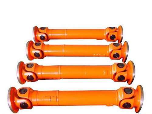
Introduction to GA-HA retractable universal coupling:
The telescopic universal coupling with sliding/needle bearing is in accordance with DIN808 standard; it can be telescopic to connect with larger shaft spacing; GA type (sliding bearing) nmax=1000min-1, HA type (needle bearing) nmax=4000min- 1; The angle of rotation of each section of the retractable universal coupling is 45°;
The advantages and structure of universal coupling:
The advantages and structure of universal coupling:
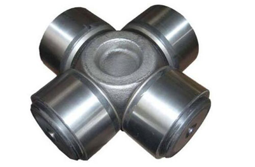
1. The cross universal joint can make the two shafts that are not on the same axis, the axis bend angle is large, and the axial movement is large, and the two shafts can rotate continuously at equal angular speed.
2. The cross universal coupling reliably transmits torque and movement.The characteristic is that it has a large angular compensation capability.
3. The cross universal coupling adopts an integral fork, which makes the transportation more reliable.
4. The cross universal coupling has compact structure, high transmission efficiency, low noise, long service life and convenient maintenance.
The cross universal coupling is suitable for transmission and transfer of mechanical shafting in metallurgical machinery, heavy machinery, petroleum machinery, engineering machinery, lifting and transportation machinery, rolling stock, light industrial machinery, precision machinery and control machinery, and other heavy machinery industries. Moment.
Assembly technology of cross universal coupling: When assembling, remove burrs and clean all parts. When assembling, it is necessary to ensure that the center lines of the middle two welding fork bearing holes are on the same plane, and the allowable difference should not exceed 1°. The spline part should be Sliding freely, joints should be rotated flexibly to clean the surface. Except for the flange end face and the end face key, apply anti-rust grease, and the rest should be painted with anti-rust primer and then painted (no paint is allowed).
The maintenance method of the cross universal coupling: regular lubrication, it is recommended to inject oil once a week, and once a day under high temperature conditions.In order to increase the service life of the universal joint, the cross shaft is adjusted 180 degrees every time it is disassembled so that the cross shaft journals can be used alternately.
The cross universal coupling has a variety of structural types: the cross universal coupling is characterized by a large angular compensation capability, a compact structure and high transmission efficiency.In practical applications, the universal joint shaft can be divided into heavy, medium, light and small according to the torque transmitted by the universal joint shaft.Cross shaft type cross universal coupling, ball cage type cross universal coupling, ball fork type cross universal coupling, bump type cross universal coupling, ball pin type cross universal coupling, Ball hinge type cross universal joint, ball hinge plunger type cross universal joint, three pin type cross universal coupling, three fork rod type cross universal joint, three ball pin type cross universal joint Shafts, hinged rod type cross universal joints, etc., commonly used are cross shaft type cross universal joints.The second is the ball cage dragon cross universal coupling, with quick locking GR and HR; the tolerance of the finished hole is H7, and the keyway, hexagonal hole and square hole can be provided according to requirements.
What types of universal joints are divided into:
According to the standard, universal joints are divided into unequal velocity universal joints, quasi-constant velocity universal joints and constant velocity universal joints.
According to the standard, universal joints are divided into unequal velocity universal joints, quasi-constant velocity universal joints and constant velocity universal joints.
① Variable speed universal joints.When the angle between the two shafts connected by the universal joint is greater than zero, the output shaft and the input shaft transmit motion at a varying instantaneous angular velocity ratio, but the average angular velocity is equal to the universal joint.
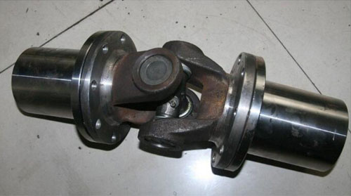
The cross shaft type rigid universal joint is composed of universal joint fork, cross shaft, needle bearing, oil seal, sleeve, bearing cover and other parts.The working principle is: one of the rotating forks drives the other fork to rotate through the cross shaft, and at the same time, it can swing in any direction around the center of the cross shaft.The needle in the needle roller bearing can rotate on its own during rotation to reduce friction.The shaft connected with the input power is called the input shaft (also called the driving shaft), and the shaft output through the universal joint is called the output shaft (also called the driven shaft).When working with an angle between the input and output shafts, the angular velocities of the two shafts are not equal, which will cause torsional vibration of the output shaft and the transmission components connected to it and affect the life of these components.
② Quasi-constant velocity universal joint.Refers to a universal joint that transmits motion at an equal instantaneous angular velocity under a designed angle, and transmits motion at an approximately equal instantaneous angular velocity under other angles.It is divided into: a) Double quasi-constant velocity universal joint.Refers to the universal joint in which the length of the transmission shaft in the universal joint constant velocity transmission device is reduced to an hour. b) Bump type quasi-constant velocity universal joint.It is composed of two universal joints and two bumps of different shapes.The two projections are equivalent to the intermediate transmission shaft and two cross pins in the double universal joint device. c) Three-pin shaft type quasi-constant velocity universal joint.It consists of two three-pin shafts, an active eccentric shaft fork and a driven eccentric shaft fork. d) Spherical roller type quasi-constant velocity universal joint.It is composed of a pin shaft, a spherical roller, a universal joint shaft and a cylinder.The roller can move axially in the groove to play the role of telescopic spline.The roller contact with the groove wall can transmit torque.
③ Constant velocity universal joint The output shaft and input shaft connected to the universal joint are universal joints that transmit motion at the same instantaneous angular velocity at all times.It is divided into:
a) Ball and fork type constant velocity universal joint.A universal joint composed of a ball fork with a raceway and a steel ball.Among them, the arc groove raceway ball fork universal joint refers to a universal joint in which the ball raceway on the sphere is an arc type.Its joint structure is characterized by arc grooves made on the driving fork and the driven fork of the ball fork. After the two are assembled, four steel ball raceways are formed, and a total of 4 steel balls are accommodated in the raceways.The centering steel ball is installed in the spherical groove in the center of the main and driven forks.Straight groove raceway ball fork universal joint refers to a universal joint in which the ball raceway on the ball fork is a straight groove raceway type.Its structural feature is that straight grooves are made on the two ball forks, and each straight groove is inclined to the center line of the shaft, and the inclination angles are the same and symmetrical to each other.There are 4 steel balls in the raceway between the two ball forks.
b) Ball cage type constant velocity universal joint.According to whether the universal joint can move in the axial direction, it can be divided into the axially non-telescopic (fixed) ball type universal joint and the retractable ball type universal joint.Structurally, the inner surface of the star sleeve of the fixed ball cage universal joint is connected with the drive shaft with inner splines, and its outer surface is made with 6 arc-shaped grooves as the inner raceway of the steel ball, and the outer raceway is made in On the inner surface of the spherical shell.After the star sleeve and the spherical shell are assembled, each of the 6 raceways is formed by a steel ball, and the cage (ball cage) makes the 1 steel balls in the same plane.The power is transmitted from the transmission shaft through the steel ball and spherical shell.The structural feature of the retractable ball cage universal joint is that the inner wall of the cylindrical shell and the outer surface of the star sleeve are made with cylindrical straight grooves, and steel balls are installed in the raceway formed after the two are assembled.The steel ball is also installed in the hole of the cage.The inner hole of the star sleeve is splined to connect with the input shaft.This structure allows the star sleeve and the simple shell to move in the axial direction relative to each other.
Previous:Nothing
Next:SWP (with telescopic long type) cross shaft universal coupling
Related Products: